Every cooled turbine blade starts as a casting, and it is one of the hardest castings in industry to get right. This post covers why blades are cast hollow, where the defects come from, what an intercooled cycle changes, and how TrustTechs supports operators who need these parts.
Why turbine blades are cast hollow
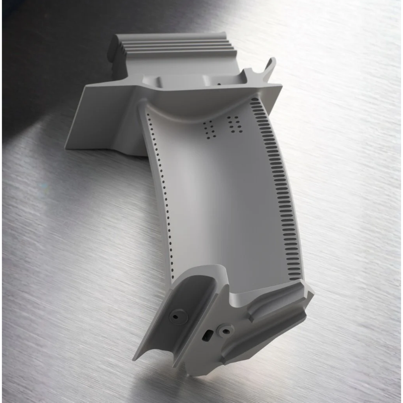
The first turbine stages of a modern gas turbine run in gas hotter than the blade metal can survive on its own. The blade stays alive because cooling air from the compressor flows through passages inside it and bleeds out through holes onto the surface.
Those passages are not machined. They are formed during investment casting by a ceramic core placed inside the mould. Molten superalloy fills the space between the core and the outer ceramic shell, and the core is then removed by leaching, leaving the hollow interior in its place.
So every cooled blade depends on three things working together: the metal and how it solidifies, the core, and the shell around it.
Growing a blade as a single crystal
The most advanced blades are cast as a single crystal (SX), with no grain boundaries. Grain boundaries are where creep and fatigue damage start at high temperature, so removing them lets the blade run hotter for longer.
The crystal is grown by directional solidification in a Bridgman furnace. The filled mould is withdrawn slowly from a hot zone into a cold one, so a solidification front moves up the blade. A helical grain selector at the bottom lets only one grain grow into the part; one study of heavy-duty blades used a withdrawal rate of 4 mm per minute.
That front has to stay steady as it passes the thick root, the platform, the thin airfoil and the ribs around the core. Every sudden change of section disturbs it, and the classic defects follow:
- Stray grains: new grains that form where the metal is locally undercooled, most often at the platform. A review of platform stray grains notes they can be enough on their own to reject a casting.
- Freckles: chains of small, randomly oriented grains on the blade surface, driven by convection of solute-rich liquid. They are common in heavy-duty gas turbine blades, and alloys rich in heavy refractory elements are more prone to them.
- Low-angle grain boundaries: slightly misaligned regions formed where dendrites growing around a core or across a platform meet again.
- Crystal misorientation: the main crystal axis drifting away from the blade axis, which changes the creep and fatigue properties the design assumed.
Not every blade is a single crystal. Many first and second stage parts on heavy-duty and industrial engines are equiaxed or directionally solidified, in alloys such as IN738LC and GTD-111, with nozzles in cobalt-based FSX-414. The core and shell problems below apply to all of them.
The ceramic core sets the internal geometry
The cooling design lives or dies on the core. It is usually a fired silica-based ceramic, chosen because fused silica has very low thermal expansion, good thermal shock resistance and leaches out well.
The core has to meet requirements that pull in opposite directions:
- Strong enough to survive: it is handled, wrapped in wax, dipped in slurry, fired and then hit by molten superalloy. Advanced cores for fine cooling passages are fragile and prone to warping and cracking.
- Stable at temperature: it must hold its shape while the metal solidifies around it.
- Easy to remove: afterwards it has to be leached out of passages that may be long, narrow and blind. Any residue blocks cooling flow.
The defect that worries designers most is core shift. The shell usually expands much more than the core during firing and preheat, so the core can move inside the mould. When metal is poured, one airfoil wall comes out thicker and the opposite wall thinner. A thin wall can oxidise or creep through early; a thick wall runs hotter than the thermal design assumed.
Foundries fight core shift with support pins, historically platinum, quartz or alumina, and with small bumpers on the core surface that hold a minimum wall thickness. Each support is a compromise with the flow path or the surface finish. Designs with several cores, such as double-wall cooling, stack these tolerances further.
Metal, shell and core fight as they cool
The superalloy shrinks far more than the ceramics around it as it cools, so the shell and core restrain the solid blade. That causes three linked problems:
- Hot tearing: cracks in the last regions to solidify, where the metal is still weak and is pulled apart.
- Recrystallisation: the restraint leaves plastic strain in the blade. During solution heat treatment, strained regions can grow new grains in a part that was meant to have none.
- Distortion: thin airfoils move out of their profile and wall thickness tolerances.
Chemistry adds another layer. Reactive elements in modern alloys, such as hafnium and yttrium, can react with silica in the core and shell and leave a damaged layer on internal walls that cannot be polished afterwards.
Intercooling raises the stakes
An intercooler removes heat between the low and high pressure compressors. The best known example is GE's LMS100, which Baker Hughes describes as the only modern industrial gas turbine to use intercooling. Intercooling cuts compressor work by 30% and allows a total pressure ratio of 42:1 while keeping compressor exit temperature within material limits. GE launched it in 2003 at 46% simple cycle efficiency.
Its high pressure core, including the high pressure turbine, comes from the LM6000. So the cycle gains land on the same kind of cooled, cast blade, and they make the casting harder in three ways:
- A steeper gradient across the wall: colder cooling air inside and hotter gas outside raise thermal stress. Life then depends heavily on wall thickness, so core shift that was tolerable before can become the limit.
- Less cooling air per blade: colder air removes more heat per kilogram, so designers use less of it. That means smaller passages, finer ribs and more film holes, all of which need thinner, more fragile core features.
- Features near the casting limit: at high pressure ratios the core flow is small and the blades are compact, but wall, rib and slot sizes cannot shrink in step.
There is also a risk specific to the cycle: blade cooling now depends on intercooler performance. If the cooling air runs warmer than designed, because of fouling or hot weather, casting variability eats into a margin the cycle has already made thinner.
Checking what you cannot see
Because the costly defects are inside the blade, foundries rely on simulation before casting and inspection after. Casting simulation tracks heat flow in the furnace, solidification, convection in the semi-solid zone and the stress between metal, shell and core. Its useful outputs map directly to the defects above: thermal gradient for stray grains, a convection criterion for freckles, and stored strain for recrystallisation.
After casting, blades are etched to reveal grains, checked by X-ray diffraction for crystal orientation, and gauged for wall thickness by ultrasonic or eddy current methods or computed tomography (CT). With so many steps in series, yield decides cost, and a new cooling design often starts at low yield.
Where casting is heading
The biggest change is in how cores are made. 3D printed ceramic cores remove core tooling and allow passages that cannot be pulled from a die. Safran Aircraft Engines has installed three Lithoz ceramic printers to produce casting cores for turbine blades, and 3DCeram has validated a printed silica core in single crystal casting.
Printing the core and shell as one integrated structure goes further, removing much of the assembly that causes core shift. Surface finish, firing stability and leachability are still open questions.
How TrustTechs supports operators
TrustTechs supplies new and refurbished hot section and compressor parts for the engines below, backed by engineering on every component. See our gas turbine parts and coatings and materials pages for the wider range.
- Siemens: SGT-100 to SGT-800, SGT-A05, V94.2, SGT5-1000F and SGT5-4000F. Turbine blades and vanes, compressor rotor blades and stator vanes, and hot section components.
- GE heavy duty: Frame 5, 6B, 6FA and 9E. Turbine buckets, nozzle segments, compressor blades and vanes, and rotor hardware.
- GE aeroderivative: LM2500. Reverse engineering and new manufacture of parts.
- Solar Turbines: Saturn, Centaur, Taurus, Mars and Titan. Turbine blades, nozzle segments, combustor liners and refurbished hot sections.
- Rolls-Royce and Centrax: 501-KB7. Spare parts packages for generator sets.
- Hitachi: H-25. Inspection spare parts packages.
For cast hot section parts, our engineering covers the issues in this post:
- Reverse engineering: 3D scanning, metallurgical and chemical analysis, and capture of internal cooling geometry.
- Casting process engineering: alloy selection, solidification simulation, and core and mould review with our partner foundries.
- Coatings: MCrAlY bond coats, thermal barrier coatings and diffusion aluminide, including internal cooling passages.
- Inspection: fluorescent penetrant inspection, dimensional and wall thickness checks, and third party inspection at the supplier or on site.
Each order is engineered against a defined specification, manufactured or sourced under controlled procedures, and delivered with a full dossier: drawings, material certificates, inspection and test reports, and traceability records.
If you need cast blades, vanes or nozzles for your fleet, send your parts list or enquiry to sales@trusttechs.ca or use our contact page.
TrustTechs is an independent engineering and service company. Manufacturer and model names are used for reference only.
Sources
- LMS100PB+ gas turbine, Baker Hughes
- GE unveils world's most efficient simple-cycle gas turbine, GE, 9 December 2003
- Grain microstructure in freckle chains of nickel-based superalloys, Microstructures, 2023
- Research progress of stray grain formation in the platform of Ni-base single crystal turbine blades, Materials Reports, 2017
- Ceramic cores raise design standards for investment casting, Foundry Management and Technology
- US Patent 5,296,308: Investment casting using core with integral wall thickness control means
- US Patent 5,050,665: Investment cast airfoil core/shell lock and method of casting
- US Patent 7,174,945: Refractory metal core wall thickness control
- US Patent 10,081,052: Casting of engine parts
- US Patent 8,506,256: Thin walled turbine blade and process for making the blade
- US Patent 11,813,669: Method for making an integrated core-shell structure
- Lithoz supports Safran with three CeraFab 3D printers, 3D Printing Industry
- 3DCeram and Design Bureau Ivchenko qualify SILICORE ceramic for investment casting, FacFox