PROJECTS
Hardware the original manufacturer left behind: Selected programmes across General Electric, Siemens Energy, Solar Turbines and Centrax fleets.
1. Combustion liners
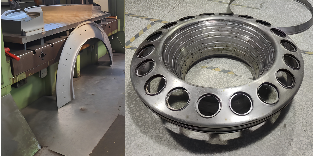
A liner is a fabrication problem before it is a materials problem. The profile has to repeat across a production run, the weld sequence has to leave the assembly round, and the cooling hole pattern has to land where the drawing says, because hole position governs wall temperature far more than wall thickness does.
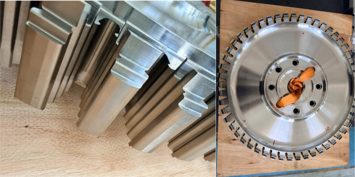
- Press tooling designed and cut for the formed segments, so the profile repeats rather than being fettled to fit on every part
- Welded sub-assemblies to qualified procedures, with distortion controlled through the weld sequence rather than corrected afterwards
- Post-weld machining to restore concentricity at the mounting and burner faces
- Effusion and dilution hole patterns produced to drawing and verified on the finished assembly
- Bond coat and thermal barrier applied to the hot side, thickness verified on production parts and not only on the first article
2. Burners and swirl assemblies
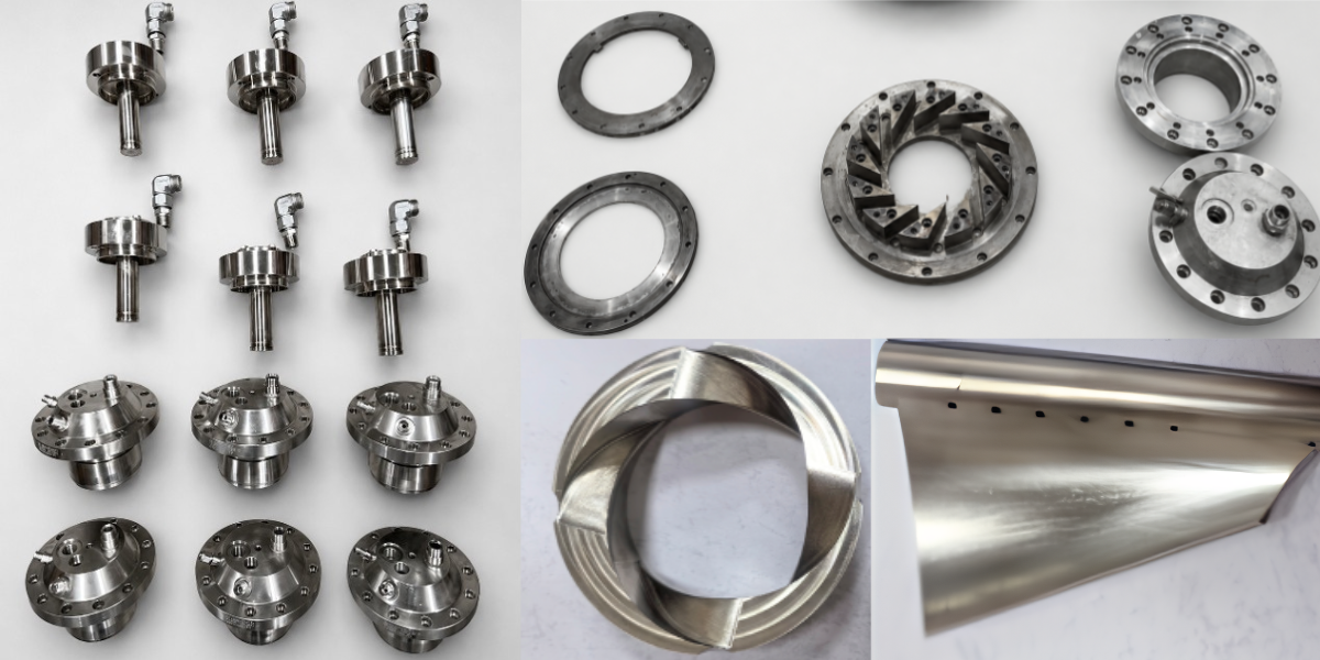
Combustion behaviour is set at the burner. Swirl number, vane angle and fuel passage geometry decide where the flame sits, and a burner a degree out on vane angle will run hot somewhere it was never designed to run hot.
- Produced as complete sets, so every burner in an engine matches and no single can drives the others
- Swirler vane angle and internal passage geometry recovered from hardware and verified against the original before anything is machined
- Flow tested across the whole set, with the spread reported rather than averaged away
- Reacting flow modelling carried out in house, so a geometry change is checked against flame position and wall temperature before it is cut
3. First stage blades in single crystal
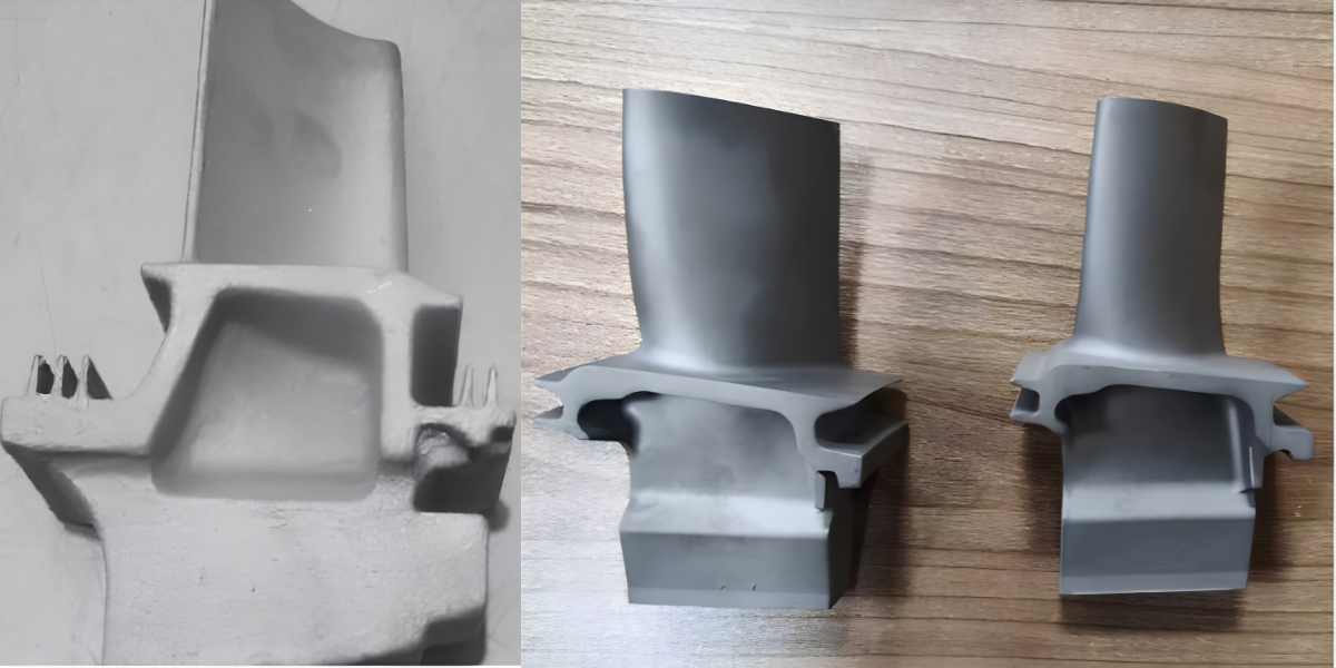
Produced in single crystal CMSX-4 with an Electron Beam Physical Vapour Deposition (EB-PVD) thermal barrier coating and Chemical Vapour Deposition (CVD) aluminising carried through the internal cooling passages.
Cooling passage geometry is the hardest thing to recover from a used part and the easiest thing to get wrong. A blade that is correct on the outside and wrong on the inside will not hold the temperature its alloy was chosen for, so the recovered internal geometry is checked by conjugate heat transfer analysis before it is committed to a core die.
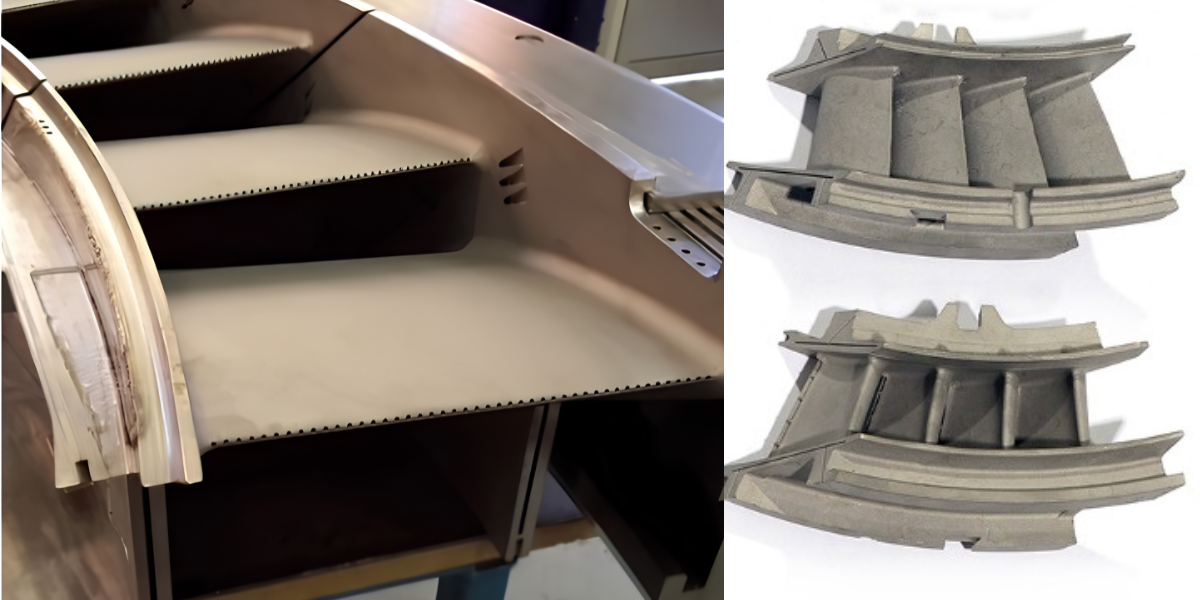
4. Nozzle guide vanes and nozzle segments
For fleets the original manufacturer no longer supports there is no drawing package to buy, so the geometry is recovered from hardware and has to be recovered accurately enough that the tool cut from it produces a segment that fits, seals and passes the right mass flow.
- Blue light scanning and Coordinate Measuring Machine (CMM) measurement, with a deviation map reported against the scanned original
- Aerodynamic verification of throat area and exit angle before tooling, because a segment can be dimensionally correct and still change the stage
- Wax dies and ceramic core tooling developed from zero, including the internal passage geometry on cooled vanes
- Cast in cobalt and nickel base alloys according to the stage, and released against a first article validated both dimensionally and metallurgically
5. Transition ducts
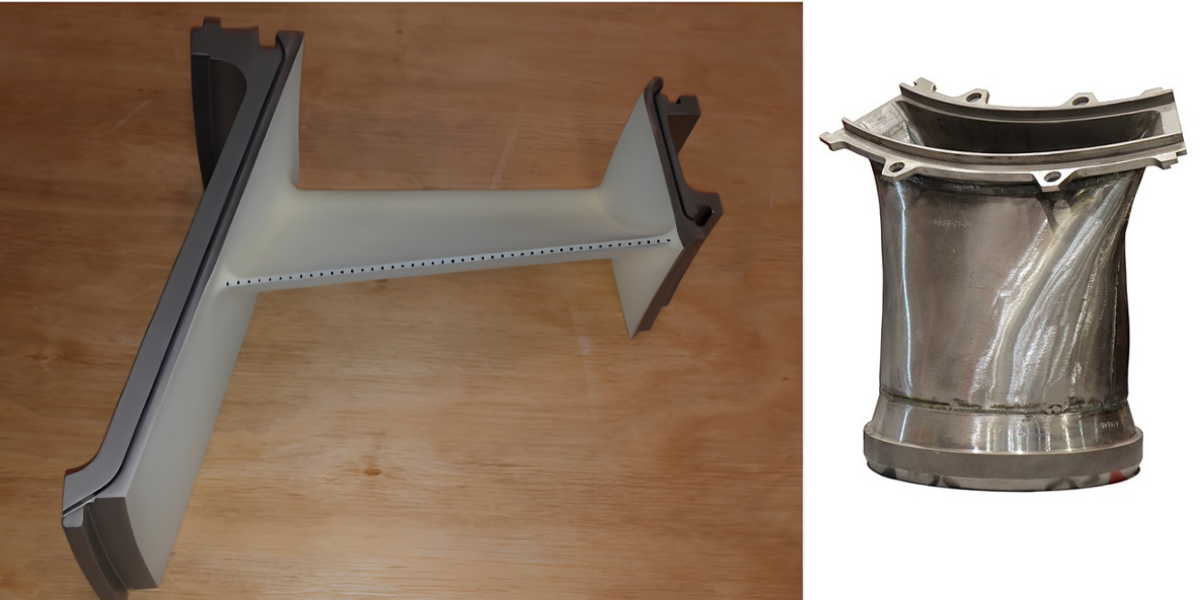
The duct takes gas from a round combustor exit to a curved turbine inlet, so it is a doubly curved fabrication that has to hold its shape while hot and stay sealed at both ends. Controlling distortion through the weld sequence is most of the work, and it is the reason ducts are usually the first part of a combustion system to come back out of tolerance.
- Formed panels and welded assembly to qualified procedures, with the sequence set to keep the exit frame flat
- Post-weld machining at the mounting frame and the aft seal land
- Non destructive testing on the weld seams before release
- Thermal barrier coating on the gas side where the design calls for it
6. Heat shields
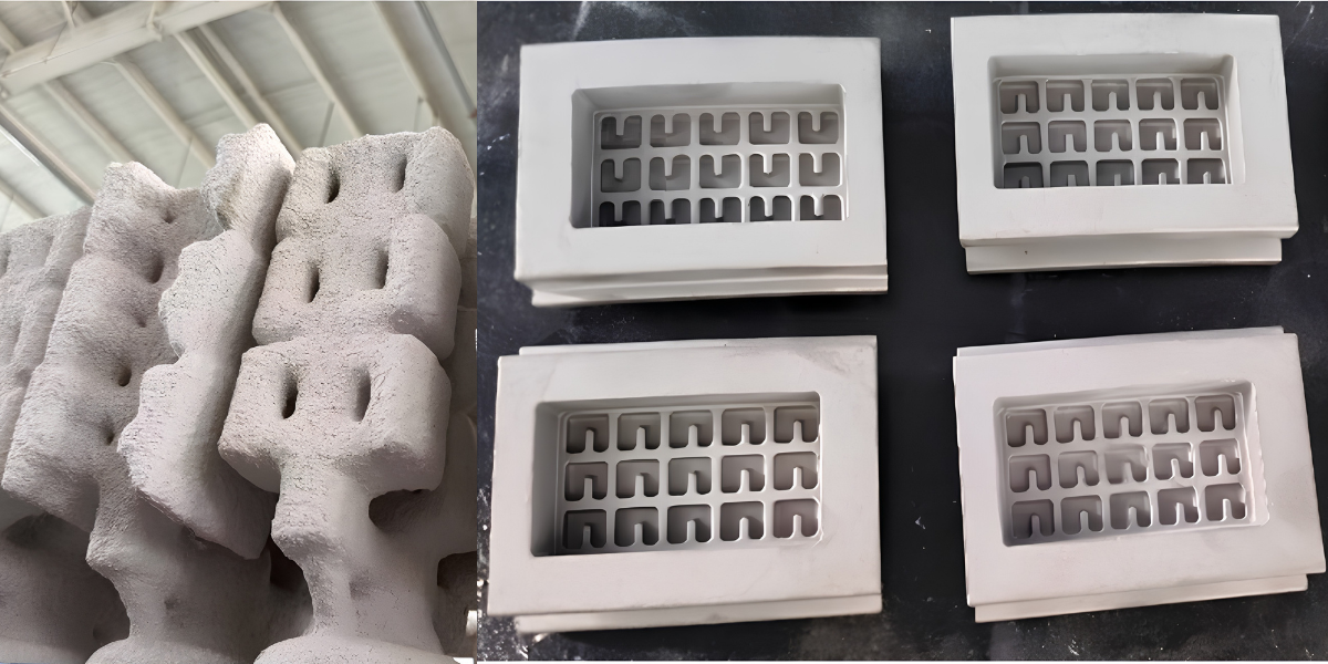
Small parts in large quantities, where the tooling economics decide everything. Quoted one at a time they are never worth making; tooled properly and cast in multi-cavity sets they become the cheapest part of a hot section to replace. That is the whole argument for carrying the tooling cost ourselves.
- Core boxes and shell moulds developed for multi-cavity casting rather than single part production
- Cooling hole rows produced and verified, since a heat shield that does not cool is a liner failure waiting to happen
- First article validated dimensionally and metallurgically before the set is released
7. Turbine discs
A disc is the one part in the hot section where a defect is not a maintenance problem. It is the highest stressed rotating component in the engine, so the material history matters as much as the finished geometry, and the case for the part has to be made in the melt shop and the forge before anyone touches a machine.
- Triple melt superalloy: Vacuum Induction Melting (VIM), then Electroslag Remelting (ESR), then Vacuum Arc Remelting (VAR), to control segregation and inclusion content
- Controlled forging and heat treatment, so grain structure and properties are set deliberately rather than inherited from the billet
- Precision rough and finish machining, with the rough stage taken far enough back to release residual stress before finishing
- High accuracy blade root slot broaching, where slot form and pitch decide whether the blade set seats evenly under load
- Mechanical testing, non destructive testing and Coordinate Measuring Machine (CMM) inspection before release